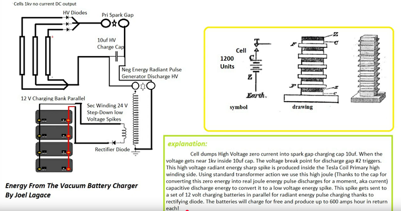
Idea: Use a very-high-voltage, ultra-low-current source (stacked Zamboni cells) to trigger a spark-gap pulse that charges a HV capacitor.
The capacitor’s energy is dumped into the primary of a Tesla/impulse transformer. The secondary delivers sharp ~24 V pulses for
experimental pulse-charging of 12 V batteries (Bedini-style). This is a speculative, educational build inspired by Tom Bearden concepts.
⚠️ High-Voltage Safety (Read First)
1 kV+ can be lethal. Work with one hand, isolate the bench, use insulated tools, and add bleeder resistors to HV capacitors.
Use proper creepage/clearance, HV-rated capacitors/diodes, and shielded spark gaps in a vented, non-flammable enclosure.
Never operate near flammable vapors; keep a fire extinguisher handy. Proceed only if you’re qualified for HV work.
HV diodes (string) → steer charge into an HV storage capacitor (e.g., 10 µF, HV-rated).
Two spark gaps:
Primary spark gap for charging control.
Breakover gap #2 that dumps the cap into the Tesla primary when threshold is reached.
Tesla/Impulse transformer (high-impedance primary, step-down to ~24 V on secondary).
Rectifier diode on the secondary → pulse DC.
12 V battery bank (parallel) for pulse-charging experiments.
Enclosure, standoffs, bleeder resistors, meter points, earth reference, and proper wiring hardware.
How It’s Supposed to Work (Explanation)
High-voltage trigger: The Zamboni stack provides ~1 kV DC at near zero current for centuries (historically very long-lived).
Capacitor charge: HV diodes feed a charge cap. Energy stored: E = ½·C·V² (e.g., 10 µF at 1 kV ≈ 5 J per dump).
Breakover event: When the cap reaches the set threshold, spark gap #2 fires, converting static charge into a brief, high-current pulse.
Impulse coupling: That pulse drives the high-impedance primary of a Tesla/impulse transformer.
Step-down spike: The transformer develops a sharp, lower-voltage (≈24 V) high-dV/dt pulse on the secondary.
Rectify & route: A rectifier sends those pulses to a 12 V battery bank for pulse charging tests (Bedini-style behavior).
Note: From a conventional standpoint, this is not free energy. You’re converting energy stored/accumulated in the HV capacitor (ultimately sourced via the Zamboni stack and the environment) into short, usable pulses.
Step-by-Step Build (Conceptual)
Assemble Zamboni Stacks
Build ~1200 paper/conductive-paint cells in series per stack; encapsulate to keep moisture out.
Verify output: aim for 1 kV+ DC (tiny current). Add bleed path through megaohm range to avoid charge float.
Install HV Diode Chain
Use HV diodes (or series strings) with total PIV comfortably above your max cap voltage.
Orient to allow Zamboni DC to charge the HV capacitor while blocking reverse discharge.
Mount Spark Gaps
Primary gap: sits between the HV diodes and the charge cap (for protective quench/conditioning per your diagram).
Breakover gap #2: across the cap → primary coil. Make it adjustable; start with a larger gap and close gradually.
Use ceramic/teflon standoffs, smooth electrodes, and a shielded, vented housing.
Wire the HV Charge Capacitor
Use a pulse-cap rated for your voltage (or series/parallel bank with balancing resistors).
Add a bleeder resistor so the cap self-discharges when idle.
Connect the Tesla/Impulse Transformer
Primary: high impedance, short leads, twisted pair to reduce stray inductance.
Secondary: step-down ratio chosen to yield ≈24 V spikes under your expected primary pulse.
Rectify and Route to Battery Bank
Place a fast diode on the secondary output; include a small RC snubber if needed to tame ringing.
Connect to a 12 V battery bank (parallel) via a fuse and current-limited path.
Initial Bring-Up
Keep batteries disconnected. Confirm the cap charges (watch voltage rise), observe breakover of gap #2 at the intended threshold.
Scope the secondary (with an isolated HV-safe probe) to confirm ~24 V impulse behavior.
Connect batteries and log pulse current/voltage. Start with short runs, check temperatures, and electrode wear.
Tuning & Notes
Gap spacing: Sets the dump threshold; too tight → frequent low-energy dumps; too wide → rare, higher-energy but stressful events.
Cap size: Energy scales with ½·C·V². Larger C = stronger dumps but slower charge from a weak source.
Primary inductance: Shapes pulse width and transformer coupling. Experiment with turns and tight coupling.
Rectification: Use fast diodes on the secondary; consider a modest storage cap if your battery prefers wider pulses.
Zamboni reality: Excellent longevity, extremely low current. Treat it as a trigger/priming source, not a power source.
Troubleshooting
No firing: Increase gap #2 distance slowly; verify HV cap really reaches threshold; check diode orientation.
Excessive heating: Lower repetition rate (wider gap or smaller C), improve electrode cooling, ensure proper snubbing.
No battery charge rise: Confirm rectifier direction, fuse continuity, and that the battery is healthy and can accept pulses.
Credits & Context
Inspired by Joel Lagace’s “Energy From The Vacuum Battery Charger” sketch and the broader Tom Bearden/Bedini pulse-charging ideas.
Longevity note: Zamboni stacks are historically long-lived (famously centuries), delivering tiny current. They serve as a zero-current trigger in this concept.