Magnetic Flux Triode Tube — What It Is & How To Build It (Step-by-Step)
Conceptual “Don Smith / Bearden–inspired” tube that stacks capacitive plates and resonant coils on a dielectric tube.
The tube is driven by a high-frequency, high-voltage (HF/HV) source (e.g., Tesla-style supply or “ion valve”) and the chained coils/plates
are arranged to encourage strong displacement currents and sharp pulses for downstream energy experiments.
This is experimental and speculative—for research/education only.
⚠️ Safety First
HV can be lethal. Use insulated tools, one-hand rule, interlocks, bleeder resistors on HV caps, and non-flammable enclosures.
Maintain generous creepage/clearance, add fuses, and keep bystanders away. If you are not qualified for HV/RF work, do not proceed.
Principle (Short Explanation)
Open-loop & nonlinearity: Instead of a closed DC loop, the HF/HV source excites the tube’s plates (capacitors) and coils (inductors), aiming for
strong field interactions and sharp transient pulses.
Triode-like layering: Alternating foil plates (acting like capacitors around the tube) and coil windings (acting like control grids) create a
stacked, multi-stage structure—hence “Magnetic Flux Triode Tube.”
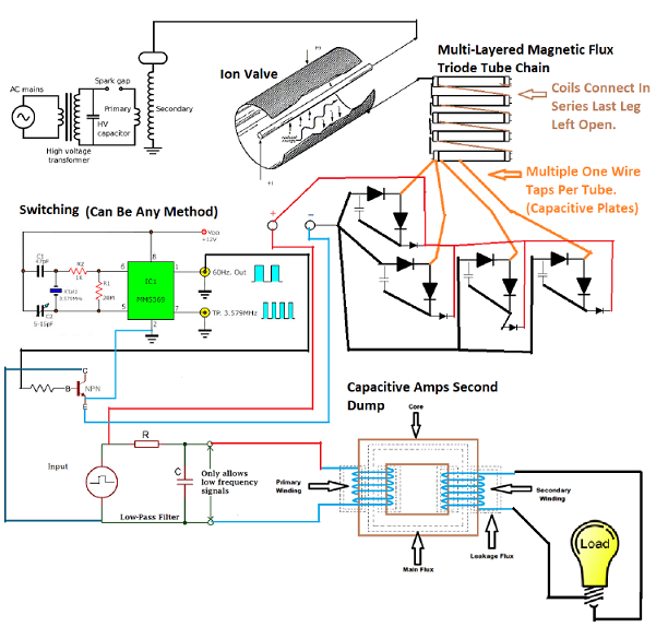
Chaining: Multiple tubes or multiple layers can be chained; last coil often left open to keep the system asymmetrical (no conventional closed current path).
Materials
Clear dielectric tube (e.g., fluorescent lamp glass or similar non-conductive tube).
Aluminum foil tape (forms the capacitive plates).
Electrical tape (vinyl) — dielectric layers and mechanical binding.
Magnet wire (enameled copper) for the coils.
Short lengths of hookup/conductor wire to bond to each foil “plate.”
Step-by-Step Construction
Prepare the tube
Clean and dry the glass/plastic tube thoroughly.
Plan where each plate and coil layer will sit; leave ~12–15 mm (½″) bare margin at each end for every foil plate.
Plate #1 (lower plate)
Wrap a band of aluminum foil tape around the tube; keep ~½″ margin from each tube end.
Attach a short conductor pigtail along the plate using foil tape so the wire is firmly bonded to the metal plate.
Dielectric wrap
Cover Plate #1 fully with a snug layer of vinyl electrical tape. This provides insulation and the dielectric gap between plates.
Plate #2 (upper plate)
Add a second band of foil tape over the dielectric, again leaving ~25 mm (1″) margin from each side of the first plate to avoid edge shorts.
Bond a second conductor pigtail to Plate #2 with foil tape.
Wrap another full dielectric layer (vinyl tape) to encapsulate Plate #2 and its lead.
Coil #1 (control winding)
Choose a winding direction (e.g., clockwise) and stick with it for all subsequent coils.
Evenly wind the magnet wire over the dielectric (on top of Plate #2). Keep turns tight and neat. Leave both coil ends accessible and initially open.
Secure with a thin layer of vinyl tape (no gaps; avoid cutting into the wire enamel).
Repeat layering
Add more plate → dielectric → coil layers as desired, preserving the same coil winding direction to maintain phase consistency.
Note: More layers can increase coupling and field strength, but excessive pressure on the glass is risky—balance layers vs. mechanical integrity.
Finish & strain relief
Overwrap the assembly with a final dielectric layer. Label each plate lead and coil lead clearly.
Add gentle strain relief to all pigtails so they don’t tear the foil or windings.
Connections (Single Tube or Chained Tubes)
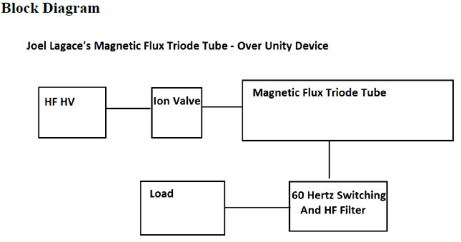
Drive (HF/HV): Connect your ion valve / HF-HV generator output to the tube’s input terminal(s) (commonly to a plate or injection node designed as the “input”).
Coil chaining: Feed the output of Coil #1 to the input of Coil #2 (e.g., down the chain “to the left”). Keep the far right end of each stage ready to connect forward.
Last coil left open: Leave the very last coil’s far end disconnected (open loop) to preserve asymmetry (per the concept).
Plates usage: Plate leads can go to measurement nodes, coupling networks, or staged capacitor banks—do not short plates together across a thin dielectric.
Downstream: Route captured pulses to rectifiers/filters or to a test load (e.g., a pulse-charge stage). Always current-limit and fuse.
Tip: Keep all HV leads short, add bleeders on any storage caps, and mind RF ground layout to reduce stray arcing and ringing.
Tuning & Use Notes
Gap & frequency: If using a spark/ion element, tune gap and drive frequency until you see clean, repeatable impulses.
Resonance: Coil turns, plate area, and dielectric thickness set resonance. Small geometry changes can make large dynamic differences.
Directionality: Keep all coils wound the same way unless you intentionally need phase inversion.
Scaling: Multiple tubes can be paralleled or cascaded; stop if heating, corona, or arcing appear—re-engineer spacing/insulation.
What It Is (In Plain Terms)
The “Magnetic Flux Triode Tube” is a layered LC structure: foil plates act like capacitors around a dielectric tube, and magnet-wire windings act as
inductors/control grids. A high-frequency, high-voltage driver excites these layers so displacement current and field coupling dominate—yielding
sharp pulses and strong near-fields for experimental energy capture or pulse-charging stages. It’s essentially a compact, multi-section
capacitor-inductor transmission structure built for asymmetrical, open-loop operation.
Block Diagram
Schematic
Wrap-Up
Build one tube carefully, characterize it (scope the fields/pulses), then replicate into a chain. Keep meticulous notes on coil turns, plate dimensions,
and spacing—these govern resonance and performance. Iterate slowly, prioritize safety, and treat all results as exploratory.