
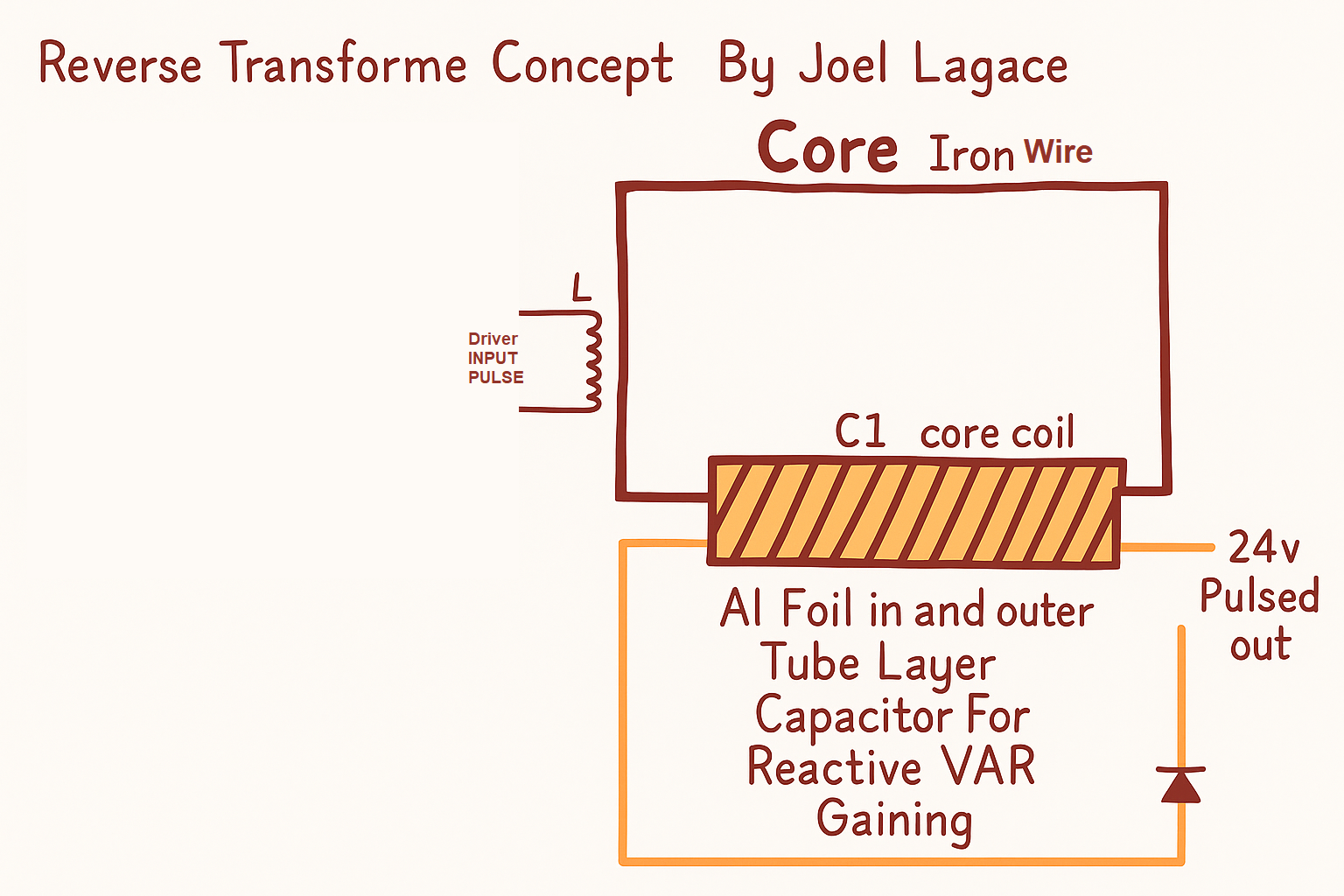
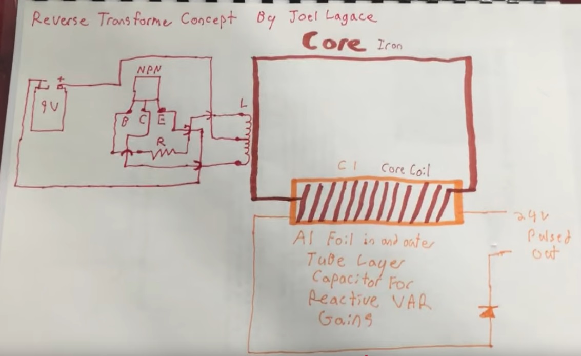
Reverse-Transformer Concept — Core-Driven Capacitive Output (Reactive VAR Gaining)
An educational walk-through of a small experimental build where the core path is treated as the primary energy channel and a
surrounding cylindrical capacitor provides the output. A simple 9 V flyback (blocking-oscillator) triggers the core,
while the foil “tube” (C1) picks up a sharp displacement-current pulse that can be rectified to ~24 V pulses.
⚠️ Safety First
- Flyback pulses can reach hundreds of volts. Keep one hand behind your back, use insulated tools, and enclose the assembly.
- Edges of aluminum foil are sharp; add tape over edges and maintain clear insulation between foil layers.
- Never connect this experiment to mains. Work from battery supplies and include fuses.
1) What “Reverse Transformer” Means Here
We are not swapping primary/secondary windings. Instead, we flip the energy emphasis: the core path (iron mass shaped as or within the winding) is impulsed, and the output is taken from a capacitive shell around that core. The foil shell acts as C1, indirectly (capacitively) coupled to the core region. The goal is strong displacement-current pulses with reduced counter-EMF back into the driver.
2) Block Diagram at a Glance
Driver (Blocking Oscillator)
- Supply: 9 V battery.
- Device: NPN power transistor (e.g., 2N3055/MJE13009 class) with base resistor
R. - Coils: feedback/drive winding
Lon the core former (center-tap to +9 V; one side to base viaR; the other to collector). - Emitter to ground; freewheel/snubber parts optional while prototyping.
Energy Head-End (Core + C1)
- Core coil: tightly wound around an iron rod/bundle; this winding is mechanically the coil but functionally the core path carrier.
- Cylindrical capacitor (C1): inner and outer aluminum-foil sleeves separated by tape/paper; length roughly matches the core region.
- Output: take one foil as C1-out, the other as return. Add a diode to select one spike polarity → ~24 V pulsed DC.
3) How It Works (Field Picture)
- Impulse: The blocking oscillator produces steep dI/dt in
L, magnetizing the iron path and launching a strong dΦ/dt. - Displacement pickup: The nearby foil cylinder sees rapid dV/dt via capacitive coupling; a brief displacement-current surge flows in C1.
- Phase quirk: The two foil plates exhibit equal-and-opposite spikes (≈180°). Measuring AC across them can show cancellation.
- Rectify one lobe: Insert a diode so only one polarity passes. The observed result is a distinct ~24 V pulse train at C1.
- Counter-EMF relief: Because the pickup is indirect (capacitive), much of the return EMF doesn’t hammer the transistor the way a tightly-coupled secondary would.
Mentions of “scalar” behavior here refer to common-mode field cancellation at the measurement nodes; keep an open, testing mindset.
4) Parts & Example Starting Values
- 9 V battery, switch, fuse (250 mA–500 mA).
- NPN transistor (e.g., MJE13009, TIP41C, 2N3055) + small heatsink.
- Base resistor
R: 470 Ω–2.2 kΩ (start ~1 kΩ; tune for clean oscillation). - Drive/feedback winding L: 80–200 turns of 26–30 AWG magnet wire on a plastic former around an iron rod/bundle.
- C1 (foil tube):
- Inner foil sleeve (bond a lead tab before wrapping), 1–2 layers of PVC tape or paper as dielectric, then outer foil sleeve with its own lead tab.
- Length: 60–120 mm; spacing: 0.2–0.5 mm dielectric. Keep edges taped to avoid corona and shorts.
- Output diode: fast UF4007/FR207 (or Schottky with adequate PIV).
- Scope probes (x10), DMM, insulating hardware.
5) Step-by-Step Build
- Prepare the core region. Fit an iron rod or tight iron-wire bundle inside a plastic tube/ former. Wind the drive/feedback coil
Lneatly; leave a center tap if using that topology. - Add the foil capacitor (C1). Wrap inner foil sleeve on the outside of the former, tape it fully, then add the outer foil sleeve. Keep a clear insulated gap between sleeves. Bring out two separate foil leads.
- Wire the oscillator. Connect +9 V to the coil center-tap; one coil end through
Rto base; the other coil end to collector; emitter to ground. Add a diode clamp/snubber if your transistor runs hot. - Add the rectifier. From the C1 “hot” foil lead, go through a diode to your load/test jack; return to the other foil. (Polarity = choose the lobe you want.)
- Power-on check. Scope CH1 on the collector (yellow), CH2 across the rectified C1 output (blue). Verify: tall flyback spike on CH1; ~20–30 V pulses on CH2.
6) Tuning & Notes
- Cancellation issue: Without the diode you may only read ~1–2 V AC due to 180° anti-phase. Keep the rectifier to select one spike.
- Capacitance matters: Longer/wider foil or thinner dielectric → larger C1 → slower but stronger pulses. Find a sweet spot for your iron/coil.
- Core options: Compare soft iron vs ferrite. Iron gives strong coupling at lower kHz; ferrite reduces eddy losses at higher kHz.
- Transistor stress: If heating, raise
R, add an RC snubber across the coil, or reduce supply. Keep leads short. - Scaling: Multiple C1 “taps” along the core (segmented sleeves) can provide several pulsed outputs; couple each through its own diode.
7) Troubleshooting
- No oscillation: Reverse the feedback leads (swap base/collector coil ends) or change
R. - Very low C1 output: Check for foil short, add/flip the diode, increase spacing symmetry, or adjust oscillator frequency.
- Transistor blows or gets hot: Add snubber/clamp, use a higher-voltage device, or reduce duty cycle.
- Noise on scope: Use x10 probes, short ground leads, and keep the build compact to reduce stray coupling.
Where to Explore Next
- Resonant conditioning: tune
LandC1toward a preferred frequency for cleaner, taller pulses. - Energy aggregation: parallel several rectified C1 taps into a storage capacitor, then DC-DC convert to your target rail.
- Low-power drivers: experiment with ultra-light oscillators; goal is milliamps of input for robust pulse output.
Some observers describe the anti-phase behavior as “scalar-like.” Treat such language as a prompt for careful measurement—not a conclusion.