Self-Recovering Bedini Circuit — Rev B
A detailed, build-oriented explainer of a Bedini-style pulse driver that keeps the coil’s magnetic
field continuously energized using two isolated supplies in push-pull. Result: dramatically reduced
counter-EMF (CEMF) stress, efficient recovery of the collapse spike, and a platform for advanced
resonance experiments.
▶ Download Full PDF Guide
Safety & Ground Rules
- Collapse spikes can reach hundreds of volts. Use fast, high-PIV diodes, fuses, and keep leads short.
- Use an isolated gate driver. Do not share logic ground with the pulse return.
- Measure with x10 probes and proper current shunts. A differential probe is ideal across the coil.
1) Why Rev B?
Traditional Bedini drivers harvest the inductor’s collapse into a separate battery. Attempts to self-loop through transformers or inverters usually lose the advantage in conversion losses. Rev B reduces those losses by keeping the coil magnetically “alive” between pulses while recovering residual kickback directly into the pulse rails.
Operating Principle (Plain English)
- Two isolated supplies (A and B) feed the same coil in the same current direction.
- 50/50 push-pull: while A is ON, B is OFF; then B is ON, A is OFF. The magnetic field never fully collapses.
- Fast diodes return the residual collapse energy to the appropriate rail each half-cycle → less waste, less stress.
Think of the coil as a magnetic flywheel: always spinning, rarely forced to stop and re-start.
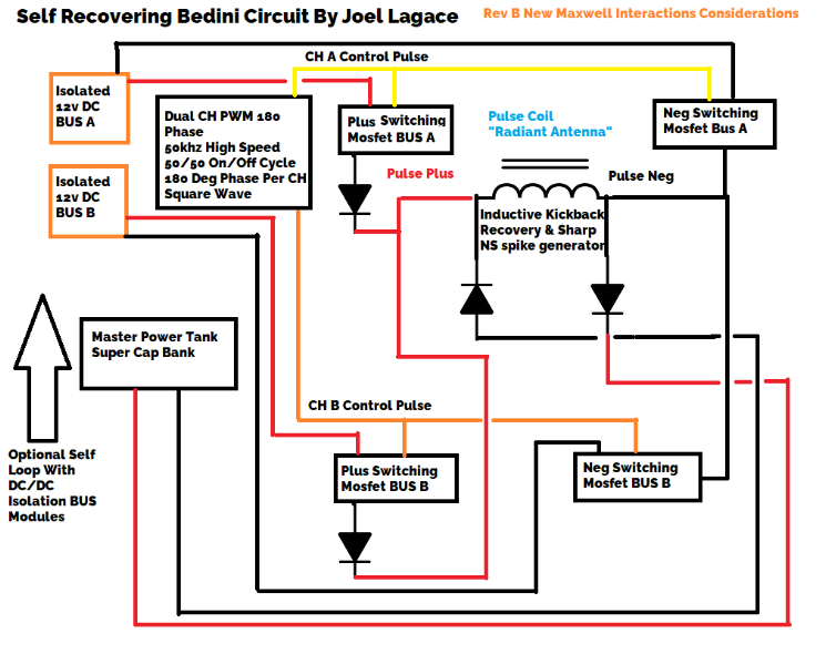
2) Schematic-Level Wiring (text)
Pulse+ (A) ── MOSFET_L ──┬──── Inductor ──── MOSFET_R ── Pulse− (A)
                          │                    │
                          │   ┌─|<|─┐         │
                          └───┤ D1  ├─────────┘   (D1 returns positive collapse to Pulse+ bus)
Pulse− (B) ───────────────┬───┤ D2  ├──────────── Pulse+ (B)  (D2 returns negative collapse to Pulse− bus)
                          │   └─|>|─┘
Isolated PWM → 15 V gate driver → both MOSFET gates (with gate resistors). Supplies A & B are isolated;
both drive the coil in the SAME direction by wiring their + to the same coil side and their − to the other.
3) Why CEMF Is Lower (and Recovery Higher)
- Continuous energization: The field is re-pumped by the other supply before it dies → smaller current delta → smaller CEMF spike.
- Smoother transitions: Proper timing reduces abrupt decays, further limiting spike amplitude.
- Energy capture: Remaining spike is diverted by D1/D2 into the rails or a recovery bus instead of becoming heat.
Advantages of a “Live” Magnetic Field
- Energy storage: The coil’s
E = ½·L·I²is reused each cycle, like a magnetic capacitor / flywheel. - Lower losses: Less collapse → less resistive heating and smaller clamp losses.
- Component relief: Push-pull shares thermal/switching burden across devices and supplies.
4) Parts & Starting Values
- Gate driver: isolated 15 V, 2–4 A peak (e.g., TC442x/IXDN + isolated DC/DC).
- MOSFETs: logic-level, low
Rds(on), ≥100 V VDS (more if your spikes are large), identical pair. - Inductor: 100–680 µH, low DCR, gapped ferrite or powdered-iron core sized for your current.
- Diodes: ultrafast/Schottky, high surge and PIV; mount tight to the coil node.
- PWM: ~4 kHz, 50/50 for push-pull (or narrow duty for single-ended experiments), very clean edges.
- Decoupling: low-ESR electrolytic + 0.1 µF film across each supply near MOSFETs.
5) Build Steps
- Lay out the power loop first. Supply A/B → MOSFETs → coil → return. Keep copper short, wide, and symmetric.
- Wire the diodes. One from coil node to the positive rail; one from coil node to the negative rail (reverse directions).
- Hook up the isolated driver. Each gate gets 5–22 Ω series resistor; keep gate loops tiny.
- Current-limit first power-up. Bench supply with limit or a series lamp.
- Probe waveforms. Verify tall but tamed collapse pulses; minimal ringing after diode action.
6) Bring-Up & Tuning
- Start at 4 kHz. Confirm 50/50 push-pull, then sweep frequency for smoothest recovery (least ringing/heat).
- Adjust inductance. Too high L → lazy pulses; too low L → brutal di/dt. Aim for crisp spikes that clamps can catch.
- Snub if needed. Add 100 Ω ∥ 1 nF from coil node to nearest rail, or a small TVS across each MOSFET.
- Thermals: MOSFETs should be cool at modest power. Heat = partial enhancement or ringing → improve gate drive/layout.
7) Measurement That Matters
- Log instantaneous power into supplies A and B and from the recovery bus:
P(t)=V(t)·I(t); integrate over identical windows. - Compare “diodes in” vs “diodes lifted” for a control. Expect lower input watt-seconds with diodes returning energy.
- Track temperature. Many “gains” are really reduced heating—legit efficiency improvements you can bank.
8) Single-Supply vs Push-Pull (at a glance)
| Aspect | Single Supply @ 99% Duty | Dual Isolated @ 50/50 Push-Pull |
|---|---|---|
| Magnetic Field | Builds, then partially collapses each cycle | Continuously energized from alternating supplies |
| CEMF | Reduced but present | Greatly reduced (field seldom collapses) |
| Energy Flow | Unidirectional | Alternating; more balanced |
| Kickback Recovery | Limited | Higher; diodes recover both half-cycles |
| Component Stress | Concentrated on one path | Shared between two paths |
| Efficiency | Improved vs low duty | Better overall due to reduced losses |
| Environmental Interaction* | Limited | Potentially higher with continuous field |
*Speculative: see next section.
Speculative Corner — Coil as an “Antenna”
- Continuous field = more chances to couple with ambient RF or other subtle fields while staying resonant.
- Sharp transitions at each half-cycle turn-off produce narrow spikes (good candidates for exotic coupling hypotheses).
- Practical takeaway: Whether you believe in ZPE or not, sharp, well-timed spikes are measurably useful for energy recovery and for driving resonant secondaries.
9) Why The Polarity Wiring Matters
Connect both supplies so their positives share the same coil end and their negatives share the other end. Then whichever supply is active, current flows in the same direction → field stays aligned and reinforced. The diodes return each half-cycle’s collapse to the correct rail.
10) Typical Questions
Q1. “If CEMF is reduced, is there still anything to recover?”
Yes—there’s still a partial collapse each half-cycle. The diodes grab that energy. Less pain, more recovery.
Q2. “How fast should I switch?”
Begin around 4 kHz, then sweep. The right frequency is the one that yields the coolest devices and the cleanest clamp on the scope.
Q3. “How do I scale power?”
Increase L and current cautiously; choose MOSFETs and diodes with generous margins; keep the layout compact; parallel modules rather than making one gigantic stage.
11) Next Steps & Variations
- Add a cap-dump from the recovery bus to a storage capacitor or battery bank; time it to the crest of the recovered pulse.
- Drive a second resonant coil from the recovered bus for staged experiments (phase-conjugate cleanup, four-wave mixing, etc.).
- Experiment with narrower duty single-ended mode as a baseline, then compare energy accounting against the 50/50 push-pull.