Better Bedini Controller — A Self-Recovering Pulse Driver
A concise, step-by-step explainer of Joel Lagace’s self-recovering Bedini-style controller. The idea: keep the classic sharp inductor spike, but recover it locally and route it back into the pulse power rails with minimal loss—no inverters, no isolation transformers, and far less penalty than full self-looping schemes.
Safety First
- Inductor collapse can create hundreds of volts. Use fast diodes rated above your worst-case spike, add fuses, and keep hands clear.
- Use an isolated gate driver for the PWM; never share control ground with the pulse power return.
- Scope with x10 probes and short grounds. A differential probe is ideal when measuring across the coil.
What Problem This Solves
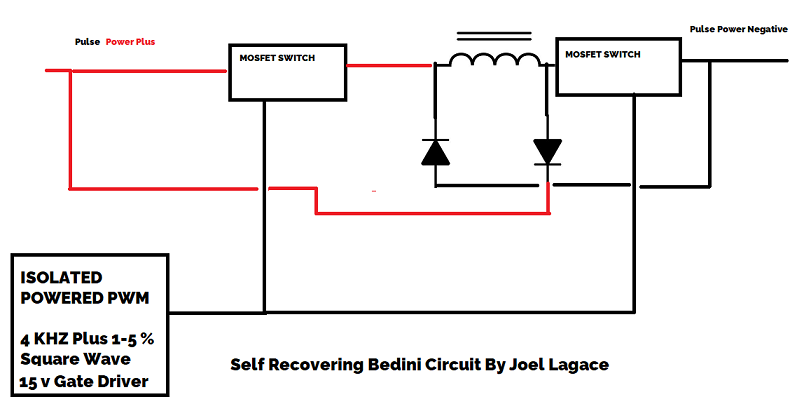
Classic Bedini setups harvest the spike into a separate battery. Attempts to loop the spike back through transformers/inverters usually lose most of the gain in conversion. Here we steer the spike directly back to the pulse rails with fast diodes, while two MOSFETs frame the inductor so the driver sees minimal counter-EMF.
How the Circuit Works (Plain English)
- Isolated PWM: A clean 4 kHz square wave at 1–5% duty from a 15 V gate driver commands both MOSFETs.
- Two MOSFET Switches: One “left” switch connects the inductor to the positive pulse rail during the brief ON time. The “right” switch references the coil to the negative rail. Together they form a pulsed path through the inductor.
- Inductor (coil): Energy is stored while ON. On turn-off, the magnetic field collapses and tries to swing the node high/low.
- Fast diodes: One diode routes the positive-going collapse into the positive rail; the other routes the negative-going collapse into the negative rail. Net effect: you keep the spike’s energy inside the pulse supply instead of dumping it as heat.
Parts You’ll Need (typical starting points)
- Gate Driver: Isolated 15 V driver module or isolated DC/DC + driver IC (e.g., IXDN, TC442x class). Output: 2–4 A peak is plenty.
- MOSFETs: Logic-level types with low
Rds(on), ≥100 V VDS rating (more if your spikes are large). Keep them identical. - Inductor: Start with 100–1000 µH, low DCR, gapped ferrite or powdered iron core, wire sized for your current.
- Diodes: Ultrafast or Schottky diodes with high surge current and fast recovery (e.g., UF4007/FR607 class for small builds; beefier parts as needed).
- Rails: A pulsed supply (battery or stiff DC source) with decoupling: low-ESR electrolytic + film cap near the switches.
Build Steps
- Lay out the power path first. Battery/rail → MOSFET_L → coil → MOSFET_R → return. Keep traces short and thick.
- Mount the diodes at the coil node. One to the positive rail (cathode to rail), one to the negative rail (anode to rail).
- Wire the isolated gate driver. Each gate gets its own series gate resistor (5–22 Ω). Tie sources to their respective rails.
- Add decoupling. 100 µF low-ESR + 0.1 µF film across the rails near the switches.
- Current-limit for first power-up. Use a bench supply with current limit or add a series lamp/NTC.
Bring-Up & What to Measure
- Set PWM: 4 kHz at ~2% duty. Verify gate swing is ~15 V with fast edges (<100 ns if possible).
- Scope the coil node: You should see a tall collapse spike at turn-off; its “tail” should be clamped by the diodes into the rails.
- Watch rail current: Compare average input current with diodes attached vs. lifted (for a moment) to confirm recovery behavior.
- Thermals: MOSFETs should run cool at low duty. If hot, check for partial enhancement or ringing—adjust gate resistors/snubbers.
Tuning Tips
- Duty sweep (1–5%). Lower duty sharpens the spike and reduces MOSFET stress; higher duty stores more coil energy—find your sweet spot.
- Inductor choice. Too much inductance → weak spike; too little → brutal di/dt and EMI. Try 100, 330, 680 µH steps.
- Snubbing. If you see ringing, add an RC snubber from the coil node to the nearest rail (start ~100 Ω // 1 nF) or a small TVS across the MOSFETs.
- Gate drive integrity. Keep gate loops tight; if edges are slow, upgrade the driver or reduce gate resistor.
Why This Is “Better”
- Local recovery: Collapse energy is redirected right back into the rails—no transformer/inverter losses.
- Isolated control: PWM stays clean and immune to ground bounce from the pulse path.
- Scalable: Add a cap-dump or battery-charge branch later without changing the core switching strategy.
Practical Checks & Suggestions
- Gate drive voltage: Your 15 V driver must fully enhance the chosen MOSFETs; partial switching = heat.
- Component ratings: Diodes and MOSFETs should exceed expected spike voltage & surge current with margin.
- Measurement hygiene: Verify energy balance over time if you experiment with feedback. Keep claims modest and data-driven.